
TTS1034 – Dual channel CAN FD/FlexRay bus device
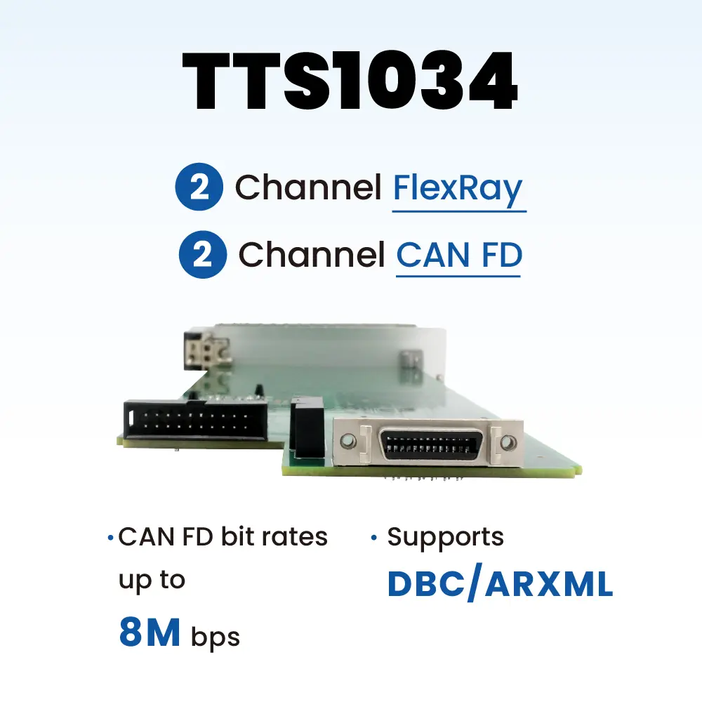
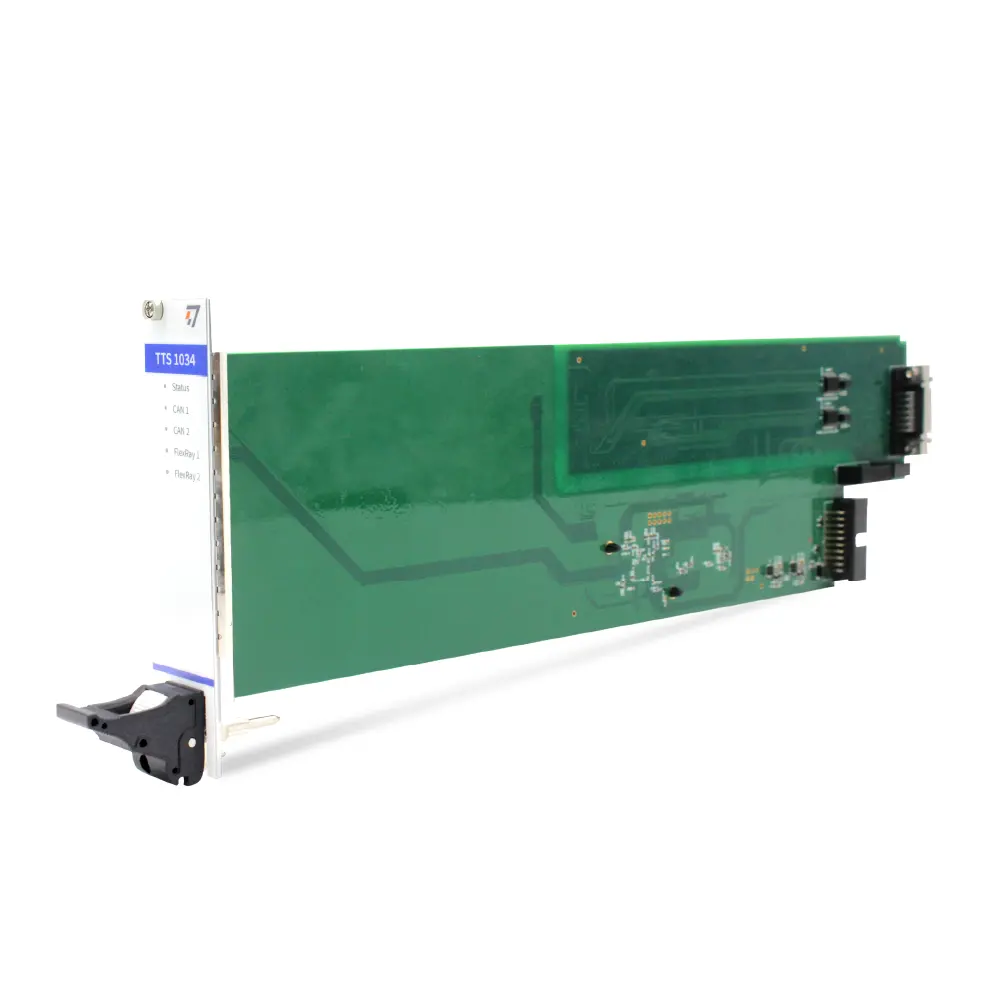
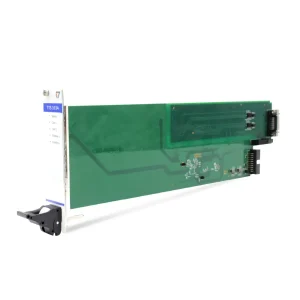
TTS1034 is a dual channel CAN FD and dual-channel FlexRay bus device launched by TOSUN. It adopts a chassis slide rail installation method, making it easy to integrate into the TOSUN TTS system.
- ARM64 Linux: tsdev
- HarmonyOS: tsdev
Related Products
Related products

TTS1034 Functions and parameters
The CAN FD 1 channel connects to the board card control bus, allowing direct control of boards within the same bus network through the CAN FD 1 channel. The CAN FD1 terminal resistor uses the resistor mounted on the TTS0001 slide rail slot, which is not software-controllable. Other parameters are the same as the TOSUN TC1034 device.
With the powerful TSMaster software, it supports loading DBC, ARXML, etc. database files, making it very convenient to monitor, analyze, and simulate CAN FD/FlexRay bus data, and it also supports functions such as UDS diagnostics, ECU flashing, CCP/XCP calibration, etc.
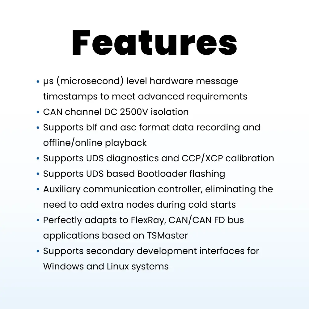
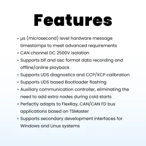
- μs (microsecond) level hardware message timestamps to meet advanced requirements
- CAN channel DC 2500V isolation
- CAN channel baud rate adjustable from 125 Kbps to 1 Mbps, and CAN FD supports a maximum of 8 Mbps
- Supports blf and asc format data recording and offline/online playback
- Supports UDS diagnostics and CCP/XCP calibration
- Supports UDS based Bootloader flashing
- Auxiliary communication controller, eliminating the need to add extra nodes during cold starts
- Perfectly adapts to FlexRay, CAN/CAN FD bus applications based on TSMaster
- Supports secondary development interfaces for Windows and Linux systems
FlexRay Functions
- Flexible configuration for communication controller buffer
- Capable to detect empty frame
- Capable of forming composite communication modes through multiple cycles (cycle multiplexing)
- Supports frame payloads up to a maximum of 254 bytes
- Supports PDUs
- Features a start up monitoring function
- Supports FlexRay message recording and replay
- Supports using two FlexRay channels as two FlexRay nodes (parallel connected)
Hardware Interface
- Pin 1 CAN_Shield
- Pin 2 CGND
- Pin 5 CAN 2_Low
- Pin 6 CAN 2_High
- Pin 7 CGND
- Pin 8 CGND
- Pin 9 FlexRay_BM 1
- Pin 10 FlexRay_BP 1
- Pin 11 FlexRay_BM 2
- Pin 12 FlexRay_BP 2
- Pin 13 CGND
- Pin 21 CGND
- Pin 22 CGND
- Pin 23 FlexRay_BP 4
- Pin 24 FlexRay_BM 4
- Pin 25 FlexRay_BP 3
- Pin 26 FlexRay_BM 3
Typical applications
Specification
| Channel | 2 x CAN FD / 2 x FlexRay |
|---|---|
| PC Interface | Converted to USB 2.0 via backplane slot |
| Communication Port Interface | SCSI 26 Pin Interface |
| Driver | Driver-free design for Windows and Linux systems, ensuring system compatibility |
| FlexRay | FlexRay channel (A and B) |
| Cold Start | Supported |
| Buffer | Each channel supports a transmit buffer of up to 1000 CAN frames |
| CAN | Supports CAN 2.0A, B protocols, compliant with ISO11898-1 standard, with baud rate 125 Kbps to 1 Mbps |
| CAN FD | Supports CAN FD that complies with both ISO and non-ISO standards, with baud rates from 125 Kbps to 8 Mbps |
| Timestamp Accuracy | 1 μs hardware message timestamp |
| CAN Terminal Resistor | Built in 120 ohm terminal resistor, software configurable |
| FlexRay Terminal Resistor | Built in 120 ohm terminal resistor, software configurable |
| Relay Type | Magnetic latching relay |
| Messages Sent per Second* | Up to 20,000 frames per second |
| Messages Received per Second* | Up to 20,000 frames per second |
| * | Single channel at 1 Mbps with a 0 byte data field |
| Isolation | CAN/FlexRay channel DC 2500 V isolation |
| Power Supply | USB power supply |
| Power Consumption | 3 W |
| Operating Humidity | 10% to 90% (non-condensing) |
| Operating Environment | keep away from corrosive gases |
During operation, make sure to correctly connect the power lines and avoid frequent plugging and unplugging.