

Related Products
You may also like…
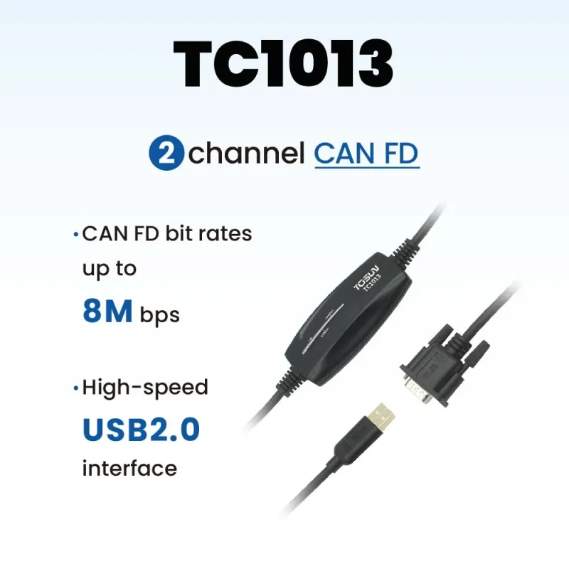
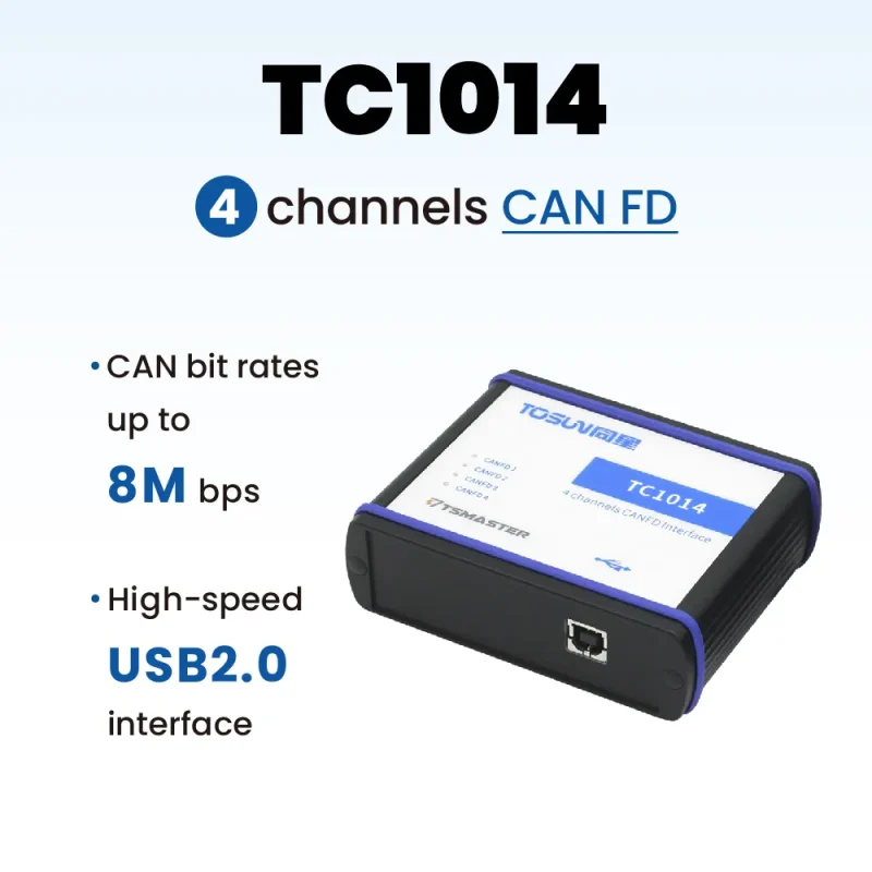
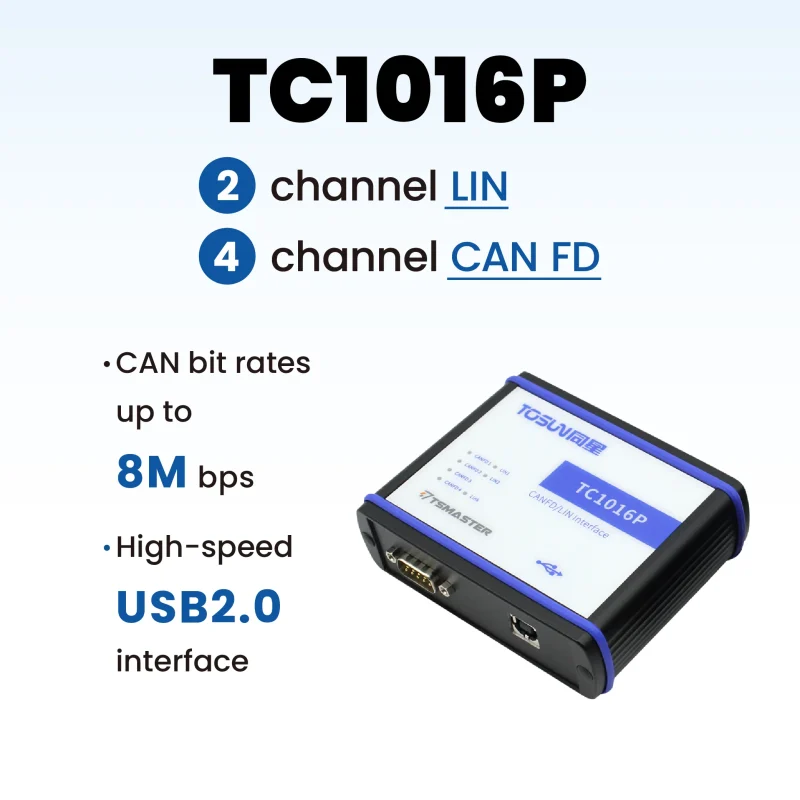
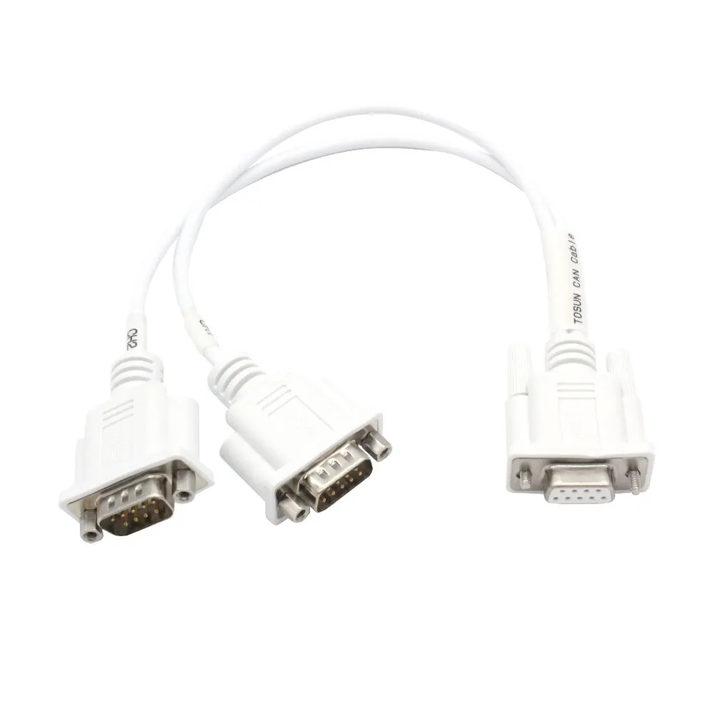
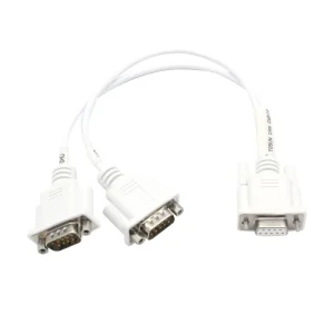
DB9 Y Splitter Cable Functions and parameters
Typical applications
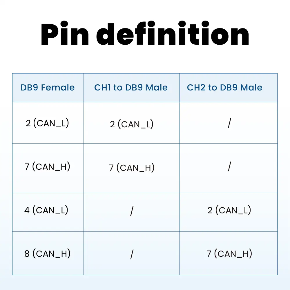
For models TC1013, TC1014, and TC1016P, the CAN FD signals from a single DB9 connectorare reconfigured. Originally, pins 2 and 7 represent CAN_L and CAN_H, while pins 4 and 8 represent another set of CAN_L and CAN_H. After reconfiguration, the signals are separated into two independent DB9 connectors, both standardized with pin 2 as CAN_L and pin 7 as CAN_H, ensuring easier connection to the DUT.
Specification
| DB9 Male | 2 (CAN_L) |
|---|---|
| CH2 to DB9 Male | 2 (CAN_L) |
| CH1 to DB9 Female | / |
Caution! Avoid Short Circuits Before using the equipment, carefully review the pin information in the product user manual.
During operation, make sure to correctly connect the power lines and avoid frequent plugging and unplugging.
During operation, make sure to correctly connect the power lines and avoid frequent plugging and unplugging.
Caution! Damage from Electrostatic Discharge (ESD) Beware! Electrostatic discharge (ESD) can potentially damage or destroy components on the card. Take preventive measures to avoid ESD and protect the components.